5.1 Collection Planning

5.1 Collection Planning

Collection planning for any remote sensing mission is a crucial step in collecting relevant and timely data. To develop a successful radar data collection plan, mission specialists need to perform a terrain and mission analysis, understand radar geometry, and know the capabilities of their radar system and the platform they will use for collection.

IMG-1919

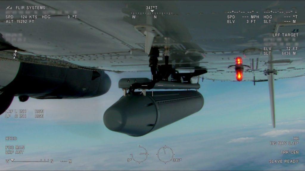
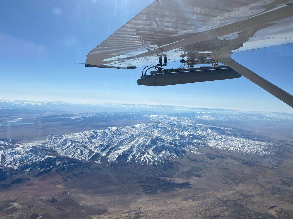
IMSAR NSP-7 Radar System on a Cessna

Pre-Mission Analysis

To optimize their results, radar operators need to perform a pre-mission analysis before they begin directing an aircraft and sensor to collect data. An analysis should consider the following factors: 

Mission Requirements

  • What intelligence or information requirements are we expecting to answer with the sensor(s)?
  • What type of imagery derived products will be required to satisfy the intelligence/information requirements?
  • Time and resources available for the data collection
  • Latest-Time Intelligence/Information-Of-Value (LTIOV), or when is the cutoff time for useful intelligence gathering?

Capabilities

  • What are the capabilities of my radar sensor?
    • Radar modes (SAR, CCD, GMTI, MMTI)
    • Minimum/maximum detection ranges
    • Flight-plan and/or auto-collect tasking options
  • Which radar frequencies are optimal for the type of collection I need?
    • X or Ku band for fine-resolution SAR/CCD imaging and MTI
    • Ultra Wideband (VHF to L band) for FOPEN/GPEN and other special collection missions
  • What aircraft is being used?
    • Manned or unmanned
    • Command and control interface between the aircraft, radar, and other sensors
  • What is the mission endurance (on-station time) available for the data collection?
    • Will it require revisit, and at what revisit rate?

Operational Environment

  • What dynamics are expected in the target area?
    • Moving or stationary targets
    • Permissive or hostile environment
    • Amount of activity or pattern of life expected at the target location
  • What is the climate or expected weather conditions?
    • Will the climate or weather conditions affect primary/secondary sensors? How?
  • What is the terrain type or topography within the collection area?
    • Land, sea, and/or littoral zone
    • Desert, vegetation, mountains, maritime, urban
    • Which grazing and look angles are needed to achieve the best possible images/MTI of the target location in this terrain?

Terrain Masking: In a pre-mission analysis, the possibility of terrain masking is an important consideration. The terrain of an area can hide, or mask, objects of interest, depending on the angle at which the data is collected. If radar energy does not reach a particular area due to terrain masking, no CCD products will be collected because the area neither receives nor returns any radar energy. Operators should look at the collection area first before making a flight plan, so terrain masking is minimized or mitigated completely by collecting at the right geometry.

SAR_example

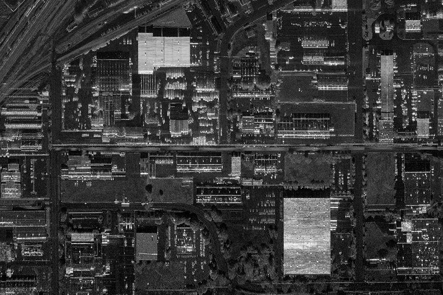
Terrain Masking: Radar Energy does not Reach the Areas Shadowed by the Terrain

Radar Geometry

When planning for a data collection, operators need to consider the angle at which the radar is transmitting to the surface being scanned. The optimal angle depends on the desired radar mode. For example, for high-detailed SAR collection, a steeper grazing angle might be optimal, but for MTI and broad coverage SAR, a shallower grazing angle is typically desired.

RadarEdu_Ch.5_Collection_Angles_SAR45
RadarEdu_Ch.5_Collection_Angles_MTI20

Example Grazing Angles for Data Collection: Fine-resolution SAR imaging collected at a 45-degree grazing angle, and GMTI data collected at a 20-degree grazing angle

For more information on the relevant angles involved in airborne SAR collection, see Interpreting Radar Imagery.

Capabilities of Radar at Different Frequencies

Aligning the goals of the ISR mission with the capabilities of the radar is essential. Different radar modes allow for different types of data intelligence. Also, different frequency bands are capable of gathering different types of information. 


Radar is most sensitive to objects that are larger than the wavelength of the transmitted signal and is mostly unaffected by relatively smaller particles. Radars operating at lower frequency bands have longer wavelengths and may achieve some degree of ground penetration (GPEN) or foliage penetration (FOPEN). For example, an Ultra Wide Band (UWB) radar system, which spans between the UHF and L bands (with wavelengths between 15 cm to 1 m), will provide better GPEN and FOPEN properties than radars with shorter wavelengths at higher frequency bands, such as Ku-band with a wavelength of about 1.6-2.0 cm. However, the shorter wavelength and higher frequency bands are generally better for making clearer images of smaller objects and features, which can lead to better target classification, tracking, and change detection.

RadarEdu_Ch.5_FOPEN

Examples of the Capabilities of Radar at Different Frequencies. Radar frequency bands with shorter wavelengths, such as Ku, bounce off leaves, while frequency bands with longer wavelengths such as UWB penetrate leaves.

Radar Modes at Different Frequencies
Radar Mode/Capability Use Ideal Frequency Bands
Fine-resolution SAR imagery Detection/classification/identification of stationary objects and general operational environment X, Ku, Ka
MTI Detection and tracking of moving targets X, Ku, Ka
CCD Monitoring of change in an area X, Ku, Ka
FOPEN Detection of stationary targets beneath foliage VHF, UHF, UWB
GPEN Detection of stationary targets below the ground’s surface VHF, UHF, UWB

For more information on radar frequencies, see Radar Characteristics in Interpreting Radar Imagery

For more information on IMSAR radar capabilities, see Multimode Capability.

Flight Plans

The angle, direction, and location of the radar relative to the surfaces being imaged matter for different types of data collection products, so pilots will need flight plans as well as skills to fly the aircraft to collect the best data.

For some SAR data products these plans are a necessity. For example, for a SAR sensor to collect CCD data, the sensor must image the same area at least twice from the same geometry using the same collection parameters. When mission specialists follow this procedure, the system can use data “pairs” to identify what has changed. Since change detection imagery requires precise positioning of the sensor while it is imaging the area, creating predetermined flight plans to match the parameters of each mission is essential.

The flight plan consists of predetermined flight “tracks” that the aircraft must follow. For best results, the platform should minimize deviations from the flight track for each collection pass.

lisa3d_flighttracks

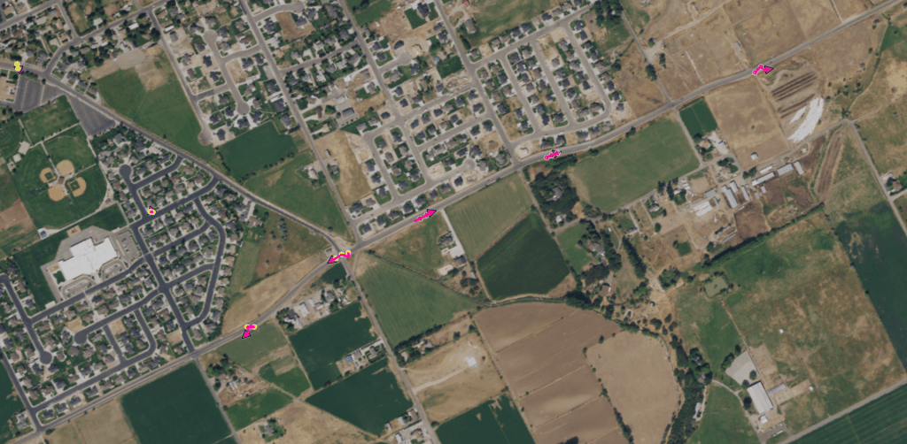
Example Predetermined Flight Tracks Shown in IMSAR’s Mission Management Software, Lisa 3D

Mission Management Software Capabilities

Operators need to be familiar with the capabilities of their mission management software before they begin a data collection. Some data collection tasks can be automatically performed by the software, but a radar operator will need to perform other tasks. Practicing tasks through simulations will help prepare operators for future collections.

Mission management software can have Command and Control (C2) functionality, Processing, Exploitation, and Dissemination (PED) functionality, or both. IMSAR’s mission management software, Lisa 3D, performs both C2 and PED functions:

Lisa 3D Software Functions
C2 Features PED Features
Radar state control 3D interactive viewing environment
Radar, datalink, and server health status Multisensor data management
Radar mode selection Timeline-based data display
Flight plan creation Forensic database/historical imagery search tools
Scan patterns selection Imagery analysis tools
Radar orientation/collection geometry Built-in imagery product templates
Command and control of other sensors Data storage, sharing & export

Lisa 3D Auto-Collect

In addition to using predetermined flight plans, radar operators also have the option to use auto-collect modes in Lisa 3D, which enables the radar to collect data over a designated area without a predetermined flight plan as long as the path is within the radar’s field of regard. Operators can choose the following collection modes within Auto-Collect:

  • SAR Imaging: Spotlight, Path (Stripmap)
  • MTI: Spotlight, Broadside, Sector Scan

Lisa 3D Visual Guidance

The Visual Guidance feature of Lisa 3D assists in flight accuracy during data collection by providing the pilot or unmanned platform operator with a real-time display of the radar’s relative position to the overall flight plan and the currently-selected flight leg. When collecting data according to a predetermined flight track, the goal is to fly as close as possible to the desired flight path with minimum roll, pitch, and crab. The Visual Guidance Plugin also features “vectoring”, which assists pilots in keeping a target in the radar’s field of regard during auto-collect missions. The purpose of vectoring in Visual Guidance is to provide the operator or pilot a real-time display of where the radar is supposed to be flown.

Plan Completion

Mission specialists armed with a thorough pre-mission analysis, a flight plan, and a basic understanding of radar geometry and their equipment’s capabilities are set up for success to collect valuable and timely intelligence with radar.

For more information on the general capabilities of Lisa 3D and IMSAR’s radar control API, see Taking Advantage of Mission Management Software.

The training sessions included with every radar purchase provide customers with more details on collection planning. For more information about IMSAR radars, contact us at sales@imsar.com


Related Content

Updated March 17th, 2022

5. How to Successfully Collect High Quality Radar Data

Knowledge Base  /  How to Successfully Collect High Quality Radar Data

5. How to Successfully Collect High Quality Radar Data

Successful radar data collection requires an understanding of collection planning and collection modes. As part of collection planning, users need to consider the terrain and other details of the operating environment. Also, they need to determine which radar sensor capabilities are best suited for their mission, and which data collection modes will be most useful. With this understanding, they can plan the collection, also taking into account how the collection flight will need to be executed by the aircraft pilots. Mission management software, like IMSAR’s Lisa 3D, can make it easier to plan flights. Additionally, the radar can be commanded to collect data over a designated area without a predetermined flight plan, as long as the area is within the radar’s field of view – this is known as autocollection.

Collection Planning

To develop a successful collection plan, mission specialists need to perform a terrain and mission analysis, have a basic understanding of radar geometry, and know the capabilities and limitations of their platforms and their radar systems. 

5_CollectionPlanning_Lisa3D

Collection Modes

Possible collection modes include stripmap, spotlight, and sector scan. Each mode has a particular set of advantages, so mission specialists need to understand how to match a mode with the type of data they need.

3_MMS_Lisa3D_SAROverlay

For more information, contact us at sales@imsar.com.


Related Content

Updated Nov. 2nd, 2021

3.2 Interpreting MTI

3.2 Interpreting MTI

Radar data used to form SAR images can be processed into other products, including MTI.  With some basic understanding, MTI products are easy to interpret and enable users to more quickly and effectively advance their missions.

MTI modes provide detections and tracks that indicate the location, direction, and speed of moving targets. Using advanced processing, MTI modes can detect slow-moving targets by extracting data from the surrounding clutter. These indicators enable a user to monitor the activity of several targets over a large area. MTI can be used on land or sea, for a wide range of target sizes including vehicles, dismounts (people), large vessels, and even small targets like fishing boats, RHIBs, and rafts. 

Key:

  • Yellow dots: Detected targets moving away from the sensor
  • Faded magenta dots: Detected targets moving toward the sensor 
  • Magenta lines: Estimated tracks of specific targets based on detections
  • Magenta arrowheads: Direction of travel of tracked targets

In the screenshot below from a GMTI data collection, several targets have been detected during a circular scan of an area of interest.

2022 GMTI Screenshot

Lisa 3D Software Display of GMTI Processing

IMSAR’s MTI modes send out energy in pulses or “chirps” at specifically timed intervals and process the returns to measure the Doppler shift of moving targets. The radar’s processing manipulates the returns to distinguish moving targets from non-moving background clutter. The system then uses complex processing technology to track moving targets and provide the user valuable data about the tracks, including the following information:

  • Relative size of targets
  • Speed of targets
  • Heading and bearing of targets

The screenshot below shows detections and tracks from a maritime data collection. The colored markings follow the same interpretation key as for GMTI processing described above.

MMTI3_Jan21

Lisa 3D Software Display of MMTI Processing from an Open-Water Data Collection

Conclusion

Automated processing of radar data into products reduces the manual processing load of image analysts. To interpret the resulting products, analysts need some basic understanding of the representations displayed on the product. With a little additional training and some understanding of their mission management software, analysts will be equipped to make effective and timely decisions in various CONOP situations.

Contact us at sales@imsar.com for more information.


Related Content

Updated Sept. 24th, 2022

3.4 Taking Advantage of Mission Management Software

Knowledge Base  /  Interpreting & Analyzing Radar Data  /  Mission Management Software

3.4 Taking Advantage of Mission Management Software

User-friendly, state-of-the-art mission management software enables radar analysts to more quickly and easily interpret data which promotes mission success. This software is available from several industry providers. IMSAR radar systems come pre-installed with Lisa 3D, IMSAR’s C2 and PED mission management software. Through its C2 functions, operators can plan flights for data collection, operate the radar, cue third-party sensors and monitor the health of the system. Through its PED functions, Lisa 3D displays data in seconds with a timeline-based workflow and intuitive search tools. Also, the software reduces operator workload by displaying data not only from the radar, but also from a variety of other sensors, such as EO/IR, FMV, and AIS.

As an alternative to using Lisa 3D for C2 functions, IMSAR radar system users have the option of using IMSAR’s Radar Control API, which allows for interoperability with other C2 ISR mission management software suites. Through the API, operators can use third-party software to slew the radar to an area of interest and immediately begin collecting data, and access data products and system status information. Additionally, IMSAR system data outputs are standards compliant, enabling data analysis in third-party PED software and the sharing of data products.

joe

Intuitive Mission Management Software Aids Data Interpretation and Analysis

IMSAR’s Lisa 3D

Lisa 3D software is a multifunctional tool from which operators can complete the following tasks:

  • Perform flight planning for multiple modes and sensors
  • Display flight data in real time
  • Analyze, annotate, store, and export data products
  • Search data from previous flights by collection time and date, sensor type, data product, collection area, or specific aircraft
  • Ingest and display geolocated data from GPX, shapefile, AIS and ADS-B simultaneously
3_MMS_Lisa3D_LineDrawing-05

With Lisa 3D, operators can send and receive messages to and from sensors, platforms, datalinks, and other operators via embedded functions, cursor-on-target, and chat messages. During operations, Lisa 3D allows the operator to monitor data collection activities, including sensor health, flight accuracy relative to flight plan, velocity, altitude, and other flight characteristics. 

lisa3d_screenshot

IMSAR’s Lisa 3D Software Features: (1) a sensor bar, (2) a heads-up display, (3) flight planning tools, (4) asset tracking tools, (5) PED tools, (6) multi-sensor coordination tools, (7) sensor status displays, (8) real-time data displays, (9) data collection planning tools, (10) a video player, (11) search tools, (12) a timeline

In addition, as the radar sensor data is being collected, Lisa 3D can display the data from multiple sensors superimposed on an optical basemap, including EO/IR imagery, FMV, SAR imagery,CCD imagery, and GMTI detections and tracks. This overlay feature allows the user to quickly compare data from multiple sensors to gain greater situational awareness of objects and targets of interest in the collection area. 

3_MMS_Lisa3D_SAROverlay

Lisa 3D with SAR Stripmap Data Overlaid on an Optical Basemap

Since IMSAR radars have multimode capabilities and can communicate with other sensors, IMSAR developed Lisa 3D to accept multiple data inputs. Lisa 3D can import data from virtually any sensor that has an IP address and an ability to export data. Lisa 3D can convert and display basemap imagery and elevation data in standard formats including CADRG, CIB, MrSID, SID, NITF, TIFF and GEOTIFF. Other data inputs Lisa 3D can be configured to accept include asset tracking such as AIS, ADS-B, or GPS data feeds, and it can maintain and monitor the line-of-site or beyond-line-of-site communications links to the aircraft. 

After mission specialists collect sensor data, they can use Lisa 3D to store the data and to search for the data by date, time, sensor, platform, location, and data type. Lisa 3D also has built-in filters to allow filtering by date and time, calendar date or date range, location, data, sensor type, and by several characteristics for GMTI playback including play type, speed, time window width, and GMTI track speed.

Interoperability with Other C2 and PED Software Suites

Several other mission management software suites are available on the market to help analysts interpret radar and other sensor data. Software products can be C2 only, PED only, or have both C2 and PED functionality. IMSAR customers have the option to use these third-party suites through IMSAR’s Radar Control API. The API software comes with a detailed Interface Control Document (ICD) to describe available commands and message functions to integrate other sensors or systems with IMSAR radars, and sample API messages to speed development and testing. Using the API, external C2 software can command SAR and MTI data collection activities, observe system health and status, and access all radar system data products: SAR and CCD imagery, and MTI detection and track streams. The API is designed with open standards for messaging and data products, allowing for transition to standardized formats such as OMS. In addition, IMSAR radar systems produce standard data products, allowing for third-party PED software use.

IMSAR Radar System Open Standards Interface
Standard Inputs Power and Ethernet, Radar API
Standard Data Products KML, Complex NITF, JPG, PNG, BMP, 

STANAG 4607 MTI Detects, STANAG 4676 MTI Tracks

Today’s radar sensors are linked to mission management software that displays data intuitively, helping to reduce the cognitive loads of mission specialists. Additionally, radar suppliers might offer training on interpreting radar imagery and related data products and provide in-field support to help new users get some hands-on experience. With these accessible resources, novice image analysts can quickly gain valuable skills to support critical missions without obtaining a specialized degree. 

Contact us at sales@imsar.com for more information.


Related Content

Updated Sept 14th, 2021

3. How Hard is it to Interpret and Analyze Radar Data?

Knowledge Base  /  Interpreting & Analyzing Radar Data

3. How Hard is it to Interpret and Analyze Radar Data?

While interpreting radar images does take some skill, it doesn’t take a specialized degree or certification. Even hiring a dedicated radar image analyst is not necessarily needed. Organizations can effectively integrate radar analysis into their current workflow. After dedicating a few hours to learning the basics, radar novices can begin analyzing data and providing valuable intelligence to accomplish their missions. 

Learners have several resources available to help ease the cognitive load as they gain experience with radar interpretation:

  • Fine-resolution SAR imagery that’s easier to interpret than traditional radar images
  • Leading-edge radar products that incorporate automated processing to eliminate several interpretive steps
  • Software interfaces that display data intuitively
  • Training courses

Interpreting SAR Imagery

SAR images from different IMSAR data collections

Radar images are non-literal, or in other words, they are a reconstruction of a scene, not a photo of one. While still useful, coarse or grainy radar images such as those above can create the perception that interpreting all radar data is complicated. However, fine-resolution SAR images make it easy to identify many common features and objects. In the image below, terrain, brush, and infrastructure are all easily discernible. Yet, some radar phenomena are at play in the image as well. For example, the bright outlines of the powerline towers in the image below are instances of a SAR phenomenon called layover, and do not accurately represent the dimensions and locations of the towers.  

SAR_ch3_Powerline

SAR image from an IMSAR data collect

Interpreting MTI and Other Advanced SAR Data Products

Through the multimode functionality of radar systems, some of the interpretation can be done automatically, so users are not flooded with data. Tools such as an MTI tracker and modes such as CCD/MCD process data automatically for specific uses. The resulting data products still need some basic explanations. For example, in the CCD/MCD data product shown below, data collected from two radar scans over the same area are combined to show changes between the two instances. CCD products display change as black highlights against an unchanged white background. MCD products display as “blue is new; red has fled” highlights, which is typical in change analysis.

ccd-1

CCD data product from an IMSAR radar data collection

Taking Advantage of Mission Management Software

Robust mission management software reduces operator workload by displaying data not only from the radar, but also from a variety of other sensors, such as EO/IR, FMV, and AIS. Radar users have several software options from various vendors, each with their own advantages. Since we at IMSAR are only experts on our own software, we can only reference it in illustration of how software can ease the cognitive load. Complete IMSAR radar systems not only include the sensor, but also data processing servers and mission computers installed with IMSAR’s C2 and PED software, Lisa 3D. This graphical software displays the data from the sensor within seconds of collection. 

Lisa3d_ch3

A screenshot from Lisa 3D, IMSAR’s C2 and PED software

Getting Training

Although radar analysts do not need formal certification or a specialized degree in radar, IMSAR recommends some training in radar basics. If an organization already has personnel familiar with intelligence sensors and products, they are ideal candidates for radar training. Individual courses are available through various institutions online or face-to-face. Radar companies might offer training also. IMSAR offers a 5-day training course with each radar system purchase. During IMSAR’s training, attendees learn basics similar to those presented in this knowledge base. Additionally, they get hands-on experience interpreting radar data using IMSAR’s built-in software for imaging interpretation and analysis, Lisa 3D. 

IMSAR’s demonstration team manager explains how training resulted in practical application for one customer:

Contact us at sales@imsar.com for more information.


Related Content

Updated July 27th, 2021

2.3 Mission Application

Knowledge Base  /  Radar Enhances Situational Awareness  /  Mission Application

2.3 Mission Application

SAR radar systems are capable of automatically turning SAR imagery into multiple real-time data products through several available modes. Due to the multimode capabilities of SAR systems, operators and analysts have considerable flexibility in switching and combining modes to produce intelligent results for multiple applications:

Battle Damage Assessment

Border Patrol

Convoy Overwatch

Counter-Drug

Counter-IED

Counter-Trafficking

Disaster Support

Force Protection

Forest Fire Detection

High Value Target Tracking

Ice Flow Monitoring

Maritime Patrol

Illegal Fishing

Oil Spill Detection

Range Clearing

Route Clearance

Search & Rescue

Maritime Patrol Focused Search

The diagram below illustrates a typical maritime patrol focused search CONOP, such as a search and rescue.

Maritime_WideArea_Steps_Blue

Maritime Patrol Focused Search CONOP

An intel hit comes in indicating that a vessel is likely inbound in a certain region during a certain timeframe, but the precise location is not known. Or, in a search-and-rescue CONOP, maritime patrol is searching for lost vessels, debris fields, life rafts, or persons at their last known location.

Mission specialists designate a search area box that will give a high probability of intercept, and fly the Maritime Patrol Radar (MPR) along the 4 edges of the search box, collecting SAR images and/or MMTI data, looking inward to minimize blind spots and time spent in transit.  

Illumination_SAR

The MPR indicates possible targets and uses MMTI mode to provide geolocated detections and tracks containing bearing and speed information.

Example of MMTI (Maritime Moving Target Indicator)

The sensor operator uses the detections and tracks to cross cue an EO/IR sensor. MPR data is compared with EO/IR and AIS data to identify the target. Relevant targets are then monitored and information is relayed to authorities. 

Counter-Drug/Counter-Trafficking in Maritime Environment

In a similar but extended CONOP, mission specialists in counter-drug or counter-trafficking efforts employ radar to accomplish steps 1 – 4 as described in the Maritime Patrol Focused Search above, with the mission continuing.

Maritime_WideArea_StepsFog_Blue

Maritime Counter-Drug/Counter-Trafficking CONOP

Fog rolls into the region. When environmental conditions such as high humidity, haze, fog, cloud cover, or darkness inhibit the effectiveness of the EO/IR system in identifying or classifying a target, sensor operators employ an Inverse SAR mode (ISAR), giving them the ability to focus on a target of interest. The radar transitions to a spotlight SAR mode on the target and begins outputting ISAR frames that can be used to identify the vessel. (In traditional SAR mapping mode, targets on water are blurred due to the vessel’s motion. The Inverse SAR mode relies on the pitching and rolling motion of the vessel to focus the imagery and identify features such as the size and number of masts).

To further detect targets, operators employ the radar to perform wide-area, coarse-resolution SAR mapping with Sector Scan to cover large swaths of the ocean and littoral environments, looking for slow and small targets. (Unlike camera systems, the radar is able to detect objects smaller than imaging resolution cell size, or sub-pixel sized objects. This allows small objects to be detected even when operating in a coarse resolution, wide-area mapping mode. Because the radar uses a tactical grade navigation solution and does not need to rely on autofocus algorithms during SAR image formation, it is able to form high quality images over low-return, water-only scenes as well as in littoral environments. This is one of the key advantages to having a multimode radar system as opposed to a conventional rotating radar.)

Illumination_SAR

Motion tracking indicates that a vessel has reached the shore. Using MMTI and ISAR for maritime and GMTI/DMTI and CCD for land, mission specialists can continue employing the radar in both littoral and inland environments to identify the source of illegal operations. Analysts combine multiple high resolution SAR passes to generate change detection (GMTI and CCD) products that highlight boat launch points along coast lines or river banks. They can also monitor unimproved air fields, roads, and other facilities to establish patterns of life and attack the network supporting illegal operations. Relevant targets are then monitored and information is relayed to authorities. 

Border Patrol

In a land-based CONOP, mission specialists employ multiple radar modes to patrol borders.

BorderCONOP_Diagram

Maritime Counter-Drug/Counter-Trafficking CONOP

Mission specialists fly a manned aircraft parallel to the border, mapping the area with SAR imaging on consecutive flights. They cover both sides of the border searching for ingress and egress points.

Illumination_SAR

An analyst uses CCD images to identify areas where illegal border crossings have occurred between flights. CCD is capable of tracking pedestrian traffic in open and mountainous terrain.

Example of CCD (Coherent Change Detection)

By using traffic patterns discovered with previous CCD passes,  the analyst identifies areas to target and employ GMTI/DMTI to detect, classify, and track any suspicious vehicle or dismount activity across large swaths of land.

GMTI

An analyst verifies activity from sensor detections by cross cueing and EO/IR sensor. 

eo-4

Mission specialists direct ground units to further investigate.

Force Protection/Convoy Overwatch/Route Reconnaissance

Unmanned aircraft equipped with radar and EO/IR can perform multiple operations to protect personnel and equipment.

ForceProtection_Diagram

Force & Equipment Protection CONOP

Mission specialists fly a single Group 1-3 UAS to perform wide-area scans with SAR imaging and GMTI to determine pattern of life.

From a ground station, an analyst directs the radar to employ SAR and CCD along patrol and supply routes to detect ground disturbances indicating areas where roadside IEDs or other hazards may have been emplaced.

An analyst uses GMTI/DMTI modes to detect and track any suspicious activity in the vicinity of forward operating bases, observation posts, patrol bases and other fixed installations.

GMTI

An analyst directs the radar to cross cue an EO/IR and/or provide the precise location and image the area of interest. 

eo-4

Ground units can further investigate or provide intelligence to appropriate authorities.

Flood/Fire/Natural Disaster

Manned aircraft equipped with complementary radar and EO payloads are ideal for monitoring natural disasters.

FireCONOP_Diagram

Natural Disaster Monitoring CONOP

In a manned aircraft, mission specialists use EO and SAR imaging to map the disaster area in real time. 

Analysts overlay the EO images with SAR images to identify flood/fire lines.

Mission specialists revisit the disaster sites at periodic intervals to update maps.

Specialists analyze the progression of flood or fire lines by comparing the SAR images from different intervals, producing CCD products.

FireCCD_Lisa3D

CCD image in IMSAR’s Lisa 3D software with analyst annotation shows the fire line of an active wildland fire.

For more information, contact IMSAR sales@imsar.com.


Related Content

Updated Mar. 22, 2021

2.2 Multimode Capability

Knowledge Base  /  Radar Enhances Situational Awareness  /  Multimode Capability

2.2 Multimode Capability

Multimode radar systems offer a variety of modes for collecting radar data and creating actionable intelligence in real time. These modes, including moving target indication and change detection, deliver data products relevant to a variety of ISR applications. Add in the capabilities of producing high-resolution imagery at great distances and covering large search areas quickly in a variety of available bands, and you have a powerhouse system equipped to give you exceptional situational awareness. 

  • High-resolution imagery at great distances
  • Rapid wide area search
  • Moving target detecting and tracking (land and maritime)
  • Change detection
  • Other modes for specific applications

High-Resolution Imagery at Great Distances

Unlike optical resolution, SAR image resolution does not degrade with increased distance. You can achieve the same image resolution whether the radar sensor is 10 km or 32 km away from the target, assuming the radar has enough power to illuminate at these distances. A SAR image is similar to a black-and-white optical image, except the pixels indicate the brightness, or magnitude, of reflection at that location. Range resolution is a function of the transmitted and received bandwidth, while azimuth resolution is a function of your synthetic aperture, which is created by “dragging” the antenna through space and time.

High-Res SAR Image

Long-Range SAR. In this urban image, roads and other features are easily distinguishable.

High-resolution SAR is a diverse capability with applications in nearly any situation in which details on the earth’s surface need to be observed (and sometimes even when details need to be observed below the surface). For example, SAR imagery has been used to monitor changes or anomalies in arctic sea ice.

SAR Image of Sea Ice

SAR Image of Sea Ice from IMSAR’s ONESAR at 0.1 m Range Resolution

Rapid Wide-Area Search

Both traditional and synthetic aperture radars have the ability to cover large areas in a relatively short amount of time. Moving Target Indication (MTI) performed by SAR is able to cover wide areas because they typically have large beamwidths, on the order of 5 to 20 degrees, which create a large footprint in a single look. By combining multiple looks in rapid succession, the radar can cover wide areas quickly. An Electronically Scanning Array, or ESA, is needed to rapidly collect these multiple looks, since an ESA has the ability to change beam location in fractions of a second.  

Maritime-Wide Area Search in Lisa3D

IMSAR Radar Wide-Area Search. IMSAR’s system software, Lisa 3D, interfaces with the radar to display radar data. Objects moving toward the sensor are marked in pink. Objects moving  away from the sensor are yellow.

SAR systems can also cover wide areas using coarse-resolution mapping.This approach is typically reserved for ocean and littoral environments when looking for slow and small targets; however, it can also be used to image over land. Unlike camera systems, radar is able to detect objects smaller than imaging resolution cell size, or subpixel sized objects. 

SAR_Littoral_Environment

Wide-Area Search

Moving Target Detecting and Tracking

Through their MTI modes, SAR radars can detect abnormalities on land or sea. Once objects are detected, the MTI modes can use multiple detections to track the target to obtain speed and heading. 

Land Targets: Ground and Dismount Moving Target Indication (GMTI/DMTI)

With GMTI/DMTI mode, operators/analysts can detect and track moving ground targets in real time, including both vehicles and dismounts. GMTI is performed by comparing the returns of the radar signal from multiple receive antennas, cancelling out the stationary background, and isolating the moving objects. GMTI outputs are simple dots that cue the operator where movement is occuring, thereby reducing the operator’s work load. GMTI processing can be especially helpful in the collection of accurate ISR in all weather, day and night, when other sensors fall short. By continuously updating radar images of a specific area, real-time geolocations of multiple targets can be obtained and displayed on a map or satellite image. When combined with SAR imagery and CCD/MCD, GMTI can be used to efficiently perform patterns-of-life analysis. 

GMTI

MTI Detects and Tracks Overlaid on an Optical Map. Actual optical imagery (left) and GMTI data overlaid on Google Earth imagery (right) of the same vehicle.

Maritime Targets: Maritime Moving Target Indication (MMTI)

SAR radars have a moving target indication mode, MMTI, specifically optimized for operations over water. MMTI mode uses Doppler to automatically search for, detect, and track moving targets and other objects in maritime and littoral environments. MMTI can be used to perform a focused search by commanding the radar to continuously monitor a preselected area of interest, or perform a wide-area search in which the radar uses a scan pattern to optimize the search area. SAR sensors can search vast areas of ocean for moving targets, perform wide-area imaging to find stationary targets, and perform high-resolution imaging to collect detailed images of targets. 

Detecting and Tracking Vessels, with AIS Data


Detection and Tracking of Vessels, with AIS Data to Corroborate. NOTE: The targets depicted in this diagram were targets of opportunity, and the detection ranges do not represent the maximum ranges of IMSAR radar system capabilities

Change Detection

Subtle changes in an area can be difficult to detect from human observation or optical images alone. Because radar sees roughness, it can detect disturbances in surfaces, such as minute changes caused by tire tracks and footprints in the dirt, which might be unobservable by the human eye. In maritime environments SAR systems are capable of processing coherent change detection along beaches and shorelines to find ingress and egress points to the water. NOTE: CCD does not work over water because the surface of the water is in a state of constant change.

CCD compares multiple SAR images of the same area collected at different times and automatically detects and highlights changes that occurred in that area between the data collections. MCD highlights magnitude changes, such as vehicles that enter or leave the scene, while CCD highlights phase changes as subtle as vehicle tracks or footprints. CCD products display as black highlights against a faded white background and MCD products as blue (new) and red (fled) highlights.

20181012_ccd


CCD/MCD. Actual CCD/MCD imagery showing vehicle tracks in black and vehicle/target changes in red/blue using a red fled, blue new coloring scheme

Other Modes for Specific Applications

SAR systems are capable of several additional specialized radar data products. The following additional modes are available with IMSAR radars, but are not necessarily exclusive to IMSAR radars.

SAR Motion Video (SMV)

Produces a live stream of the radar imagery, which is replayable, and provides a context that might be lost in individual still images. The output of SMV is similar to that of Full Motion Video (FMV), although it typically updates at a slower rate.

SMV and Full-Motion Video (FMV) of the Same Intersection. SMV (left) supplements the imagery produced by FMV (right) by providing continuous, real-time sensor coverage when FMV cannot, such as during cloud cover, night skies, or Degraded Visual Environments (DVE).

ISAR

IMSAR has advanced its radars’ multimode capabilities to include a real-time Inverse Synthetic Aperture Radar (ISAR) processing mode, which will enable high resolution imaging of moving vessels for measurement and classification. The ISAR mode enhancement, in which two-dimensional, high resolution images of maritime targets can be generated, is a valuable advantage in maritime applications, since it relies on the motion of targets on water rather than the movement of the radar to generate images. This mode provides target imaging in all weather, which is especially important in maritime environments since they are notorious for poor weather conditions.

ISAR Data from Maritime Collection with the IMSAR NSP-7. These ISAR images (left: 0.1m resolution) and (right: 0.3m resolution) were taken of the craft pictured in the center, with the following specifications: 10,000′ AGL, 25-degree depression/grazing angle, 4 mile standoff range, sunny conditions. 

Sector Scan

Sector scan mode is a subset of Moving Target Indication. This mode allows for a maximum amount of surface area to be covered by the radar, so it is especially useful for wide-area searches. 

Sector Scan

Sector Scan Mode. The red shape represents the Field of Regard for the radar, with the radar being located at the center of the small circle (upper left-hand corner). The green shading shows the radar’s current scanning area, and the green outline represents the sector scan area the radar is preset to cover.

FOPEN

Since foliage canopies create barriers that can reflect signals and prevent them from reaching the objects and terrain below, nefarious actors often conceal infrastructure and illegal activity below the canopy. Optical and infrared sensors do not penetrate through foliage and can even be reflected by other, less dense barriers including clouds and smoke. In low-frequency UWB radar systems, long wavelength signals naturally penetrate foliage and detect man-made objects, such as buildings and vehicles, directly through the foliage. FOPEN applications include stemming illegal activities such as deforestation and drug manufacturing and trafficking activity.

For more information, contact IMSAR sales@imsar.com.


Related Content

Updated May 14th, 2021

2.1 Operating Environment

Knowledge Base  /  Radar Enhances Situational Awareness  /  Operating Environment

2.1 Operating Environment

A highly adept and robust technology, radar will perform well under nearly any environmental condition. Not only is it an effective tool in both land and maritime environments, but it has a unique way of illuminating the world, giving us power to see beyond the visible. It illuminates darkness, sees through clouds, and penetrates smoke.

Radar sensors complement EO/IR sensors well, adapting to environments in which optical and infrared systems are compromised. Unlike an optical system, a radar system transmits and receives its own energy signal and doesn’t rely on the sun, which means it can provide the same quality data products during the day and at night. While infrared systems can generate nighttime images by sensing the heat signatures of objects, the infrared frequencies are affected by degraded visual environments, such as in smoke and dust, and in adverse weather conditions such as in clouds, fog, and precipitation. In contrast, the signal transmitted and received by radar systems uses a significantly longer wavelength than that of optical and infrared sensors, which allows the radar to penetrate obscurants such as clouds, fog, dust, smoke, and precipitation. Because of these characteristics, radar systems can generate fine-resolution imagery, detect changes, and track moving targets during the day, at night, and in adverse weather conditions and degraded environments.

RadarEdu_Clouds_Diagram

Illumination in the Dark

It’s obvious that when the sun isn’t shining, optical sensors are limited without some alternative light source. Since a radar system provides its own energy source, it can transmit and receive energy to create images at night. Another advantage of radar producing its own illumination reveals itself even in clear daylight. Users can simply choose to collect data from optimum look angles to extract the maximum amount of detail from their target, as opposed to waiting for the sun or another energy source to be at the correct angle for the sensor to get “the shot”. In other words, with radar you can position the energy source where you want it, when you want it there. The freedom of various collection angles is not possible with a passive sensor.

For example, notice the different angles of the shadows in a comparison of the optical and SAR images below. Assuming the same north-to-south orientation of the optical and radar sensors when these images were taken, the radar sensor illuminates the areas where the sun casts shadows. The radar’s orientation could be changed to illuminate a scene from any angle, shedding light on any areas darkened by the earth’s orientation to the sun.

Illumination_EO

Optical image with shadows to the northeast

Illumination_SAR


SAR image of the same scene with illumination of areas where the sun cast shadows in the optical image

Clarity Through Adverse Weather Conditions

As an example of radar’s ability to work in adverse weather, in late 2020, one of IMSAR’s customers gave us feedback on the all-weather capabilities of our NSP radar systems. They were supporting an exercise on a manned aircraft equipped with an NSP-7 system in front of coalition partners. The radar was able to identify and track targets when other sensors failed due to the low-visibility weather conditions.

The side-by-side comparison of optical and radar images during inclement weather in the figure below shows the advantages of using radar sensors to complement EO/IR sensors.

SMV_FMV_Maritime


Still Shots from SMV and FMV Data Collections in a Maritime Environment. Real-time data was collected from both an IMSAR NSP radar system’s SMV mode (upper screen) and an MX-15 optical FMV camera (lower screens) of a large container ship. Although the optical images were at times obscured by fog, the IMSAR radar penetrated the fog to obtain SMV images. (Note: The optical camera images show telescopic on the left and wide angle on the right).

Penetration of Smoke

Another experience shows radar’s ability to operate in degraded visual environments. IMSAR deployed radar sensor packages to the Indianola Type 1 and 2 Incident Command Post during the Coal Hollow Fire event in Utah County, Utah during August 2018. The fire burned 31,661 acres of land in mountainous terrain and threatened highway corridors, railways, utilities, and residential areas. The radar sensors demonstrated smoke-penetrating imagery in a side-looking configuration. IMSAR assisted the Type 1 and 2 Incident Commanders by providing over 200 square miles of radar imagery and 750 square miles of high and medium resolution EO imagery of the rapidly expanding wildfire area. As a result of the data collection, approximately 320 miles of active and inactive fire perimeter were marked and mapped and 34 individual hotspots (active fire areas) were detected using the IMSAR EO, MWIR, and SAR/CCD data.


Radar Produces Clear Imagery in Smoky Conditions. Optical images on left show the degraded visual conditions during the Coal Hollow Fire. Radar images overlaid on optical images on the right show radar’s ability to penetrate the smoke and produce clear images of the terrain below.

Effective Data Processing on Both Land and Sea

Radars are capable of collecting imaging and data for advanced processing in both land and maritime environments. Radar energy transmitted to the surface of a body of water often reflects in many other directions, and in many cases the reflected energy does not return to the sensor. This phenomenon creates a dark canvas on which reflected energy from floating objects will show very distinctive returns.

SAR_Littoral_Environment

Littoral Environment

MMTI in Lisa 3D


Maritime Image Displayed in IMSAR’s Lisa 3D Software. Actual maritime data from IMSAR’s radar system shows the detection of multiple vessels within a single scene.

Environmental Testing and Performance 

The following test results of our NSP-7 radar system illustrate the environmental robustness of radar. The system was tested for operation in extreme environments to MIL-STD-810G requirements, as summarized in the table below. Furthermore, because the radar is housed inside of a weather tight housing, this acts as a radome, which simplifies integration for many aircraft.

Parameter Value
Operational Temperature 

(Airborne Equipment)

-32 to 54 degrees C @ all altitudes (Tx off)

-32 to 37 degrees C ambient (Med Tx power)

-32 to 13 degrees C ambient (High Tx power)

Operational Temperature 

(Ground Equipment)

5 to 35 degrees C
Storage Temperature -40 to 85 degrees C
Temperature Shock 2.78 degrees C per minute
Operational Vibration Anticipated to meet Mil-STD-810G Method 514.6 Procedure I Operational Vibration Annex D Category 13 Propeller Aircraft
Shock Load in Longitudinal Direction 20g
Shock Load in All Other Directions 10g
Rain MIL-STD-810G Method 506.5 Procedure I (4 inches blowing at 40 mph for 30 minutes)
Salt Spray Surface treatment for protection
Humidity 100% relative humidity

Results from MIL-STD-810G Testing Performed on the NSP-7 Radar System 

Contact IMSAR at sales@imsar.com for more information.


Related Content

2. Radar Enhances Situational Awareness

2.2 Multimode Capability

2.3 Mission Application

3. How Hard is it to Interpret and Analyze Radar Data?

3.4 Taking Advantage of Mission Management Software

3.2 Interpreting MTI

5. How to Successfully Collect High Quality Radar Data

5.1 Collection Planning

Updated Mar. 22, 2021

2. Radar Enhances Situational Awareness

Knowledge Base  /  Radar Enhances Situational Awareness

2. Top 3 Ways Radar Enhances Situational Awareness

Decision makers involved in Intelligence, Surveillance, and Reconnaissance missions rely on relevant and timely data to gain situational awareness. Within their areas of responsibility, they seek to gain a tactical advantage over any situation, to ensure the safety of their personnel, and to decisively accomplish their objectives. Today’s multi-INT radars are masters at facilitating situational awareness, as exhibited in the following characteristics: 

  • Operating Environment: Intelligence gathering day or night, in DVEs, on land or sea
  • Multimode Capability: High-resolution imagery at great distances, rapid wide-area search, moving target detection and tracking, and change detection
  • Mission Application: Flexibility in combining modes for various CONOPS
NSP-7 on the King Air C90

IMSAR NSP-7 radar system integrated on a King Air C90

Operating Environment 

The quality of a radar image does not change with the weather or the time of day. Whether over land or in a maritime setting, radars meet the demands of any mission, providing actionable intelligence even through degraded visual environments, such as smoke, haze, or fog.

Example of FMV (Full Motion Video)
Example of SMV (SAR Motion Video)

An FMV image (left) and an IMSAR SMV image (right) of the same intersection during the same conditions

Multimode Capability

With the ability to automatically process data into near real-time imagery or detection and tracking intelligence, SAR systems are capable, robust tools for ISR applications. They offer multiple modes that can be switched between rapidly with a few clicks of a mouse. The operator can use MTI to rapidly scan a large area, then key in on targets and switch to high resolution SAR imaging all on the same orbit or track. If multiple images have been collected (over land) on the same location, the operator can also switch to change detection imagery to see where the target may have moved to or traveled from. These capabilities combine to create powerhouse systems equipped to deliver exceptional situational awareness.

Data products from the multiple modes of IMSAR radars

Mission Application

Since today’s radars can produce data in multiple modes, users have considerable flexibility in switching and combining these modes to produce intelligent results for multiple military and commercial applications, such as counter-trafficking, maritime patrol, and route reconnaissance.

Mission CONOPs: For example, a combination of SAR imaging and CCD modes can be used to produce intelligent data for border protection or counter-drug or counter-trafficking missions.

Capitalizing on radar’s inherent capabilities gives ISR strategists a powerful tool for situational awareness. Contact us to learn more at sales@imsar.com


Related Content

Updated Mar. 22, 2021

1. When We Say Radar

Knowledge Base  /  When We Say Radar

1. What Does IMSAR Mean When We Say Radar?

RADAR: RAdio Detection And Ranging. Like laser, modem, scuba, and sonar, the acronym first used by the US Navy in 1940 has become such a common word that it’s no longer written in all caps. The definition of radar has come a long way from its initial application for military use during World War II to its current everyday applications from automotive safety to biomedical practice. Radar typically operates within the electromagnetic spectrum in frequency bands between 200 MHz to 36 GHz. As radar designers and manufacturers work to solve human challenges in several areas, radar has a myriad of sizes, shapes, levels of complexity, and applications within those bands. So, what does IMSAR mean when we say “radar”?

We Mean SAR  

Synthetic Aperture Radar is a radar that, through movement, electronically emulates a much larger antenna, resulting in finer resolution imagery through a much smaller radar. Typically, SAR systems are airborne and side-looking. They are designed to scan the earth’s surface, collecting high-resolution imagery and multiple other geospatial data products.

Additionally, inherent in radar is its ability to see in the dark and through degraded visual environments, such as smoke, clouds, and fog. With this advantage, SAR systems complement and work with other platform sensors, such as EO/IR cameras, for a true all-weather solution.

Cessna_MMTI_RadarInAction

IMSAR Radar System Performing Maritime Surveillance from the Wing of a Small Airborne Platform

We’re Talking Low SWaP

Historically, SAR systems have been relegated to satellites and large, specialized aircraft due to their size, weight, power and expense. When we say “SAR,” we’re talking about small size, weight, and power (SWaP) sensors for Group 1-5 unmanned and manned turboprop platforms. These smaller SAR systems incorporate the same advanced capabilities as the radar systems of the past, enabling a host of new aircraft to access the benefits that radar has to offer.

Today’s Airborne SAR Systems are Low-SWaP, as illustrated here with podded SAR systems mounted on the King Air B200, a turboprop-sized manned aircraft (left), and the Skyfront Perimeter 8, a Group 2 unmanned platform.

We’re Thinking Multimode 

The surface scanning and imaging ability of SAR systems allows for multiple interpretations of data through various radar modes. Standard radar system capabilities include SAR imaging, coherent change detection, and moving target indication modes.

SAR Imaging: Creates multiple high-resolution black-and-white images. The systems can perform both focused high-resolution imaging and coarse-resolution wide area searches.

CCD: Compares multiple SAR images of the same area collected at different times and automatically detects and highlights changes that occurred in that area between the data collections.

MTI: Performs rapid scans over a wide area, detects and tracks moving targets in real time, on land or on sea.

Furthermore, SAR is capable of performing more advanced modes such as Interferometric SAR (IFSAR), Inverse SAR (InSAR), Forward Looking SAR (FLOSAR), and Air-to-Air MTI (AMTI).

Examples of Radar Data Products (clockwise from upper left): SAR imaging, coherent change detection (CCD), maritime moving target indication (MMTI), and ground moving target indication (GMTI).

We’re Implying Multi-INT

Like pieces of a puzzle, when the multimode capabilities of SAR systems are intelligently combined, they provide a big-picture view to inform operational decisions. Synthetic Aperture Radar technologies are used for multiple military and commercial ISR applications:

  Counter Drug   Maritime Patrol   Search & Rescue
  Range Clearing   Convoy Overwatch   Route Clearance / Counter-IED
  Oil Spill Detection   Disaster Support   Illegal Fishing
  Ice Flow Monitoring   High Value Target Tracking   Battle Damage Assessment
  Border Patrol / Counter Trafficking   Force Protection   Forest Fire Detection 

We Plan to Democratize Radar

Radar, with its multitude of modes, capabilities, and unique benefits, is an important aspect of the overall approach to protecting Life, Liberty, and the Pursuit of Happiness. We seek to eliminate barriers that have prevented customers from looking to radar to augment or solve their ISR problems. We recognize that what we are able to do is only possible through the tremendous effort of all of those that have gone before us and all those that continue to push forward in the study and development of radar and other enabling technologies. At IMSAR, we seek to help democratize radar, making it more usable, affordable, and accessible. 

Ryan Smith, founder, president and CEO of IMSAR, and Larry Moore, executive vice president, further explain what it means to democratize radar.

If you would like to connect with us to learn more about radar, please contact us at sales@imsar.com.


Related Content

Updated Feb. 17, 2021