KNOWLEDGE BASE CONTENTS
Knowledge Base / Radar Enhances Situational Awareness / Operating Environment
2.1 Operating Environment
A highly adept and robust technology, radar will perform well under nearly any environmental condition. Not only is it an effective tool in both land and maritime environments, but it has a unique way of illuminating the world, giving us power to see beyond the visible. It illuminates darkness, sees through clouds, and penetrates smoke.
Radar sensors complement EO/IR sensors well, adapting to environments in which optical and infrared systems are compromised. Unlike an optical system, a radar system transmits and receives its own energy signal and doesn’t rely on the sun, which means it can provide the same quality data products during the day and at night. While infrared systems can generate nighttime images by sensing the heat signatures of objects, the infrared frequencies are affected by degraded visual environments, such as in smoke and dust, and in adverse weather conditions such as in clouds, fog, and precipitation. In contrast, the signal transmitted and received by radar systems uses a significantly longer wavelength than that of optical and infrared sensors, which allows the radar to penetrate obscurants such as clouds, fog, dust, smoke, and precipitation. Because of these characteristics, radar systems can generate fine-resolution imagery, detect changes, and track moving targets during the day, at night, and in adverse weather conditions and degraded environments.

Illumination in the Dark
It’s obvious that when the sun isn’t shining, optical sensors are limited without some alternative light source. Since a radar system provides its own energy source, it can transmit and receive energy to create images at night. Another advantage of radar producing its own illumination reveals itself even in clear daylight. Users can simply choose to collect data from optimum look angles to extract the maximum amount of detail from their target, as opposed to waiting for the sun or another energy source to be at the correct angle for the sensor to get “the shot”. In other words, with radar you can position the energy source where you want it, when you want it there. The freedom of various collection angles is not possible with a passive sensor.
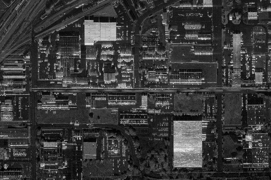
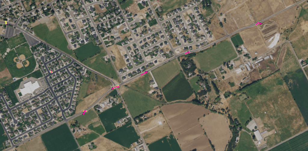
For example, notice the different angles of the shadows in a comparison of the optical and SAR images below. Assuming the same north-to-south orientation of the optical and radar sensors when these images were taken, the radar sensor illuminates the areas where the sun casts shadows. The radar’s orientation could be changed to illuminate a scene from any angle, shedding light on any areas darkened by the earth’s orientation to the sun.


Clarity Through Adverse Weather Conditions
As an example of radar’s ability to work in adverse weather, in late 2020, one of IMSAR’s customers gave us feedback on the all-weather capabilities of our NSP radar systems. They were supporting an exercise on a manned aircraft equipped with an NSP-7 system in front of coalition partners. The radar was able to identify and track targets when other sensors failed due to the low-visibility weather conditions.
The side-by-side comparison of optical and radar images during inclement weather in the figure below shows the advantages of using radar sensors to complement EO/IR sensors.

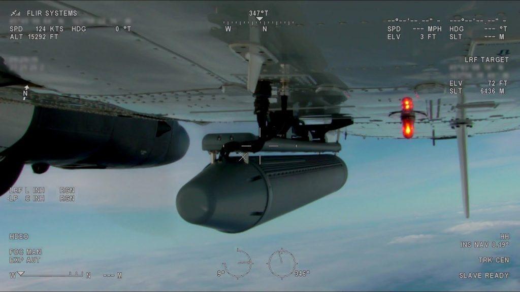
Still Shots from SMV and FMV Data Collections in a Maritime Environment. Real-time data was collected from both an IMSAR NSP radar system’s SMV mode (upper screen) and an MX-15 optical FMV camera (lower screens) of a large container ship. Although the optical images were at times obscured by fog, the IMSAR radar penetrated the fog to obtain SMV images. (Note: The optical camera images show telescopic on the left and wide angle on the right).
Penetration of Smoke
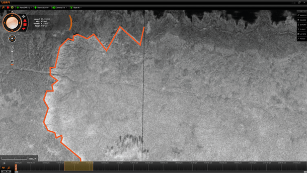
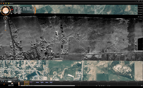
Another experience shows radar’s ability to operate in degraded visual environments. IMSAR deployed radar sensor packages to the Indianola Type 1 and 2 Incident Command Post during the Coal Hollow Fire event in Utah County, Utah during August 2018. The fire burned 31,661 acres of land in mountainous terrain and threatened highway corridors, railways, utilities, and residential areas. The radar sensors demonstrated smoke-penetrating imagery in a side-looking configuration. IMSAR assisted the Type 1 and 2 Incident Commanders by providing over 200 square miles of radar imagery and 750 square miles of high and medium resolution EO imagery of the rapidly expanding wildfire area. As a result of the data collection, approximately 320 miles of active and inactive fire perimeter were marked and mapped and 34 individual hotspots (active fire areas) were detected using the IMSAR EO, MWIR, and SAR/CCD data.
Effective Data Processing on Both Land and Sea
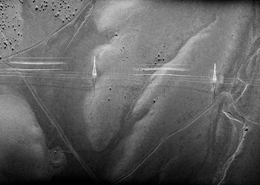
Radars are capable of collecting imaging and data for advanced processing in both land and maritime environments. Radar energy transmitted to the surface of a body of water often reflects in many other directions, and in many cases the reflected energy does not return to the sensor. This phenomenon creates a dark canvas on which reflected energy from floating objects will show very distinctive returns.

Littoral Environment

Environmental Testing and Performance
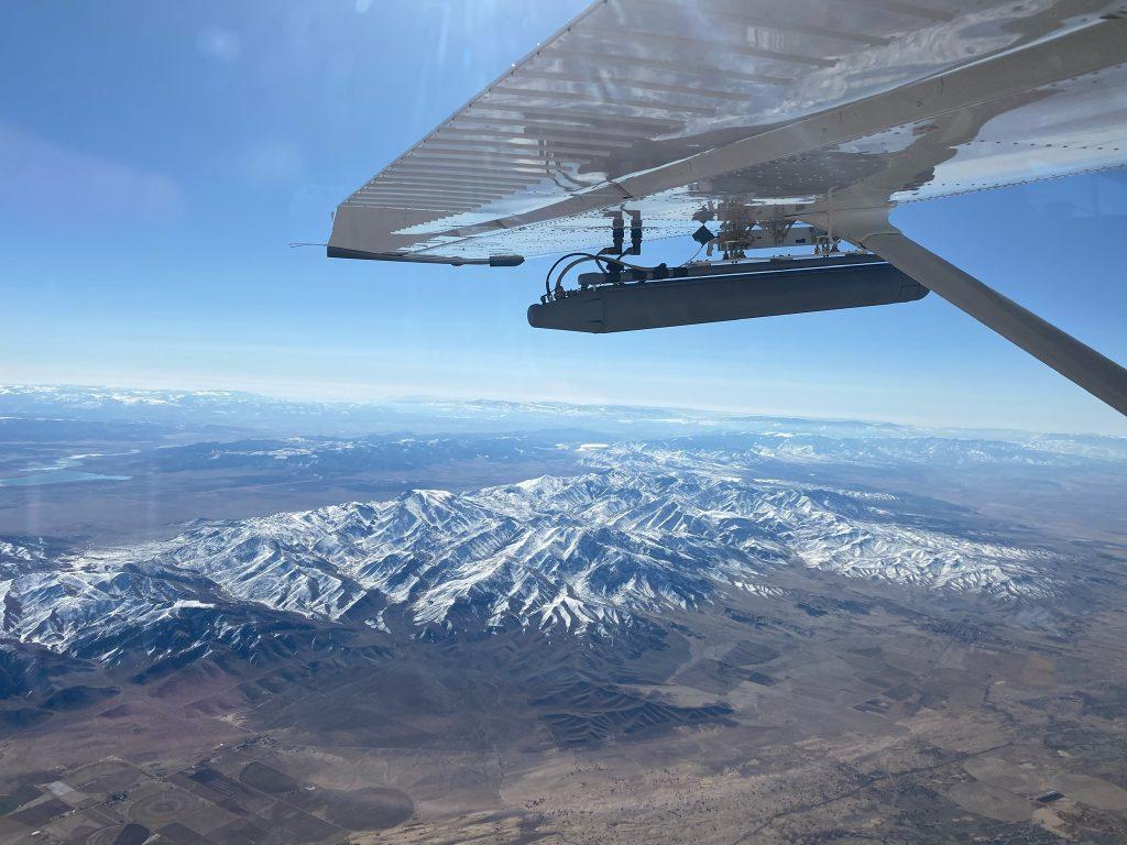
The following test results of our NSP-7 radar system illustrate the environmental robustness of radar. The system was tested for operation in extreme environments to MIL-STD-810G requirements, as summarized in the table below. Furthermore, because the radar is housed inside of a weather tight housing, this acts as a radome, which simplifies integration for many aircraft.
| Parameter | Value |
| Operational Temperature
(Airborne Equipment) |
-32 to 54 degrees C @ all altitudes (Tx off)
-32 to 37 degrees C ambient (Med Tx power) -32 to 13 degrees C ambient (High Tx power) |
| Operational Temperature
(Ground Equipment) |
5 to 35 degrees C |
| Storage Temperature | -40 to 85 degrees C |
| Temperature Shock | 2.78 degrees C per minute |
| Operational Vibration | Anticipated to meet Mil-STD-810G Method 514.6 Procedure I Operational Vibration Annex D Category 13 Propeller Aircraft |
| Shock Load in Longitudinal Direction | 20g |
| Shock Load in All Other Directions | 10g |
| Rain | MIL-STD-810G Method 506.5 Procedure I (4 inches blowing at 40 mph for 30 minutes) |
| Salt Spray | Surface treatment for protection |
| Humidity | 100% relative humidity |
Results from MIL-STD-810G Testing Performed on the NSP-7 Radar System
Contact IMSAR at sales@imsar.com for more information.
Related Content
2. Radar Enhances Situational Awareness
2.2 Multimode Capability
2.3 Mission Application
3. How Hard is it to Interpret and Analyze Radar Data?
3.4 Taking Advantage of Mission Management Software
3.2 Interpreting MTI
5. How to Successfully Collect High Quality Radar Data
5.1 Collection Planning
Updated Mar. 22, 2021