 DATASHEET
A low-SWaP radar system capable of performing Synthetic Aperture Radar (SAR) imaging from a stratospheric Uncrewed Airborne System (UAS) or balloon platform.
STRATOSPHERIC MULTIMODE SAR RADAR
PSAR
SEE AT NEW HEIGHTS
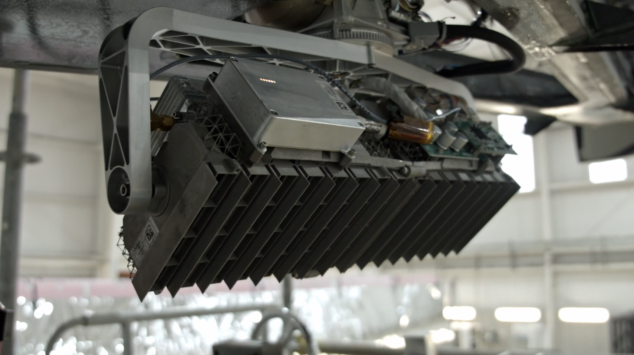
The Pseudo-satellite Synthetic Aperture Radar (PSAR) system was designedas a high-altitude radar system, capable of operating within the stringent Size, Weight, and Power (SWaP) requirements of High-Altitude, Long Endurance (HALE) platforms. IMSAR combined our military-proven NanoSAR technology with a lightweight, additive manufactured array.
The reduced SWaP is achieved by using the low-loss, additive manufactured, aluminum, single-array antenna as a structural and thermal component of the system, in addition to its role in transmitting and receiving the radar signals. The innovative design sufficiently reduces the space and weight required for the radar system to allow the radar to integrate into HALE platforms that were previously unable to carry radar sensors, including both Uncrewed Aircraft System (UAS) and balloon platforms.
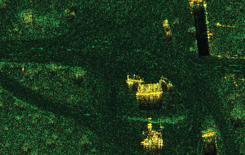
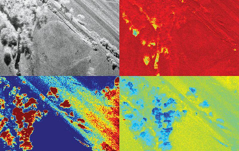
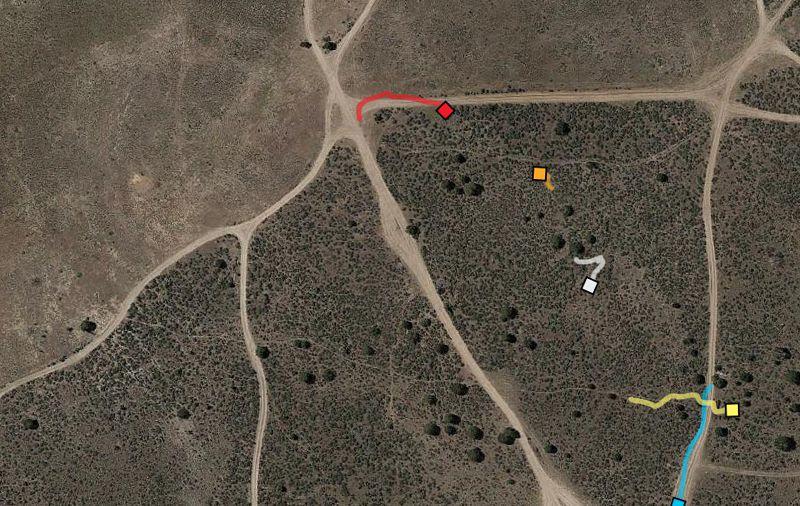
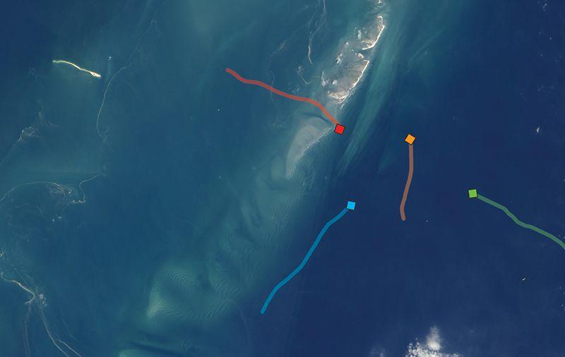
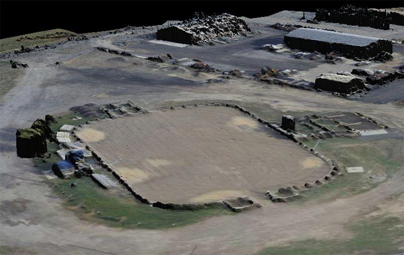
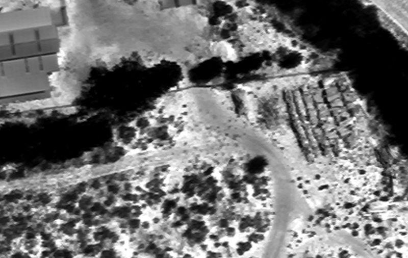
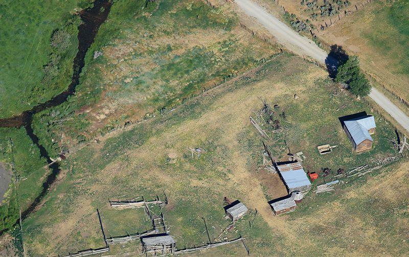
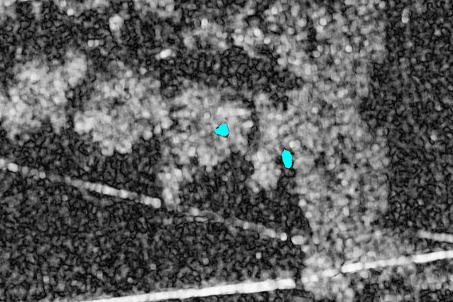
PSAR IMAGE SAMPLES
TYPICAL USES FOR PSAR
Typical uses for IMSAR’s PSAR System can include:
- Disaster Preparation & Response
- Emergency Rescue
- Livestock & Wildlife Monitoring
- Military Surveillance
- Border Security
- Tracking Applications
- Search & Rescue Operations
- Counter Drug Trafficking Operations
- Wildland Fire Monitoring
For more information about PSAR and other products, contact us at information@imsar.com or call IMSAR sales at 801.798.8440.